Introduction
Cooling of the core insert is the greatest problem in most moulding applications. With no core cooling, heating of the core is therefore unavoidable. Current fabrication methods place severe limitations on the configuration of the cooling channels used for heat withdrawal. Using Metal Additive Manufacturing (M-AM) processes, Conformal Cooling Inserts can be fabricated with ease. As a result, your cycle times shorten while you produce parts with lower residual stresses. This article will shed some lights upon the design and manufacturing of Conformal Cooling Channel (CCC’s) using M-AM.
Basics of Injection Moulding Process
Injection Moulding is the process of forcing melted plastic in to a mould cavity. Once the plastic has cooled, the part can be ejected. Injection moulding is often used in mass-production and prototyping and is a relatively new way to manufacture parts, the first machines appearing in the 1930’s.
There are six major steps in the injection moulding process namely:
1. Clamping:
An injection moulding machine consists of three basic parts: the mould, plus the clamping and injection units. The clamping unit holds the two halves of the injection mould together during the injection and cooling.
2. Injection:
During the injection phase plastic material, usually in the form of pellets, is loaded into a hopper on top of the injection unit. The pellets feed into a cylinder where they are heated until they reach molten form. Within the heating cylinder there is a motorized screw or ram that mixes the molten pellets and forces them to end of the cylinder. Once enough material has accumulated in front of the screw, the injection process begins. The molten plastic is inserted into the mould through a sprue (channel), while the pressure and speed are controlled by the screw.
3. Dwelling:
The dwelling phase consists of a pause in the injection process. Once the molten plastic has been injected into the mould, the pressure is applied to make sure all of the mould cavities are filled.
4. Cooling:
The plastic is allowed to cool to its solid form within the mould.
5. Mould Opening:
The clamping unit is opened, which separates the two halves of the mould.
6. Ejection:
An ejecting rod and plate eject the finished piece from the mould. The unused sprues and runners can be recycled for use again in future moulds.
Conformal Cooling
In-mould part, cooling is the most time-consuming part of the plastic injection moulding process – reduce the time for part cooling and you will increase production speed whilst achieving higher quality moulded parts with less scrap. A variety of techniques have been used to maintain even temperatures over the years, using methods such as bubblers, heat pipes and complex drilling operations using laminated blocks. These, however, are cumbersome, time consuming and can limit the useful life of a mould. Drilled cooling channels are also limited to straight lines, no matter what the part geometry.
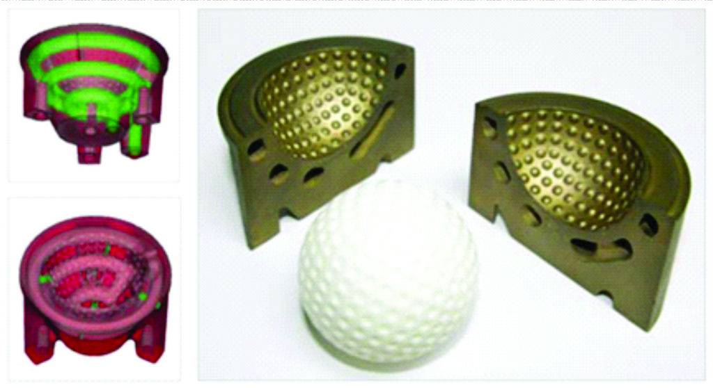
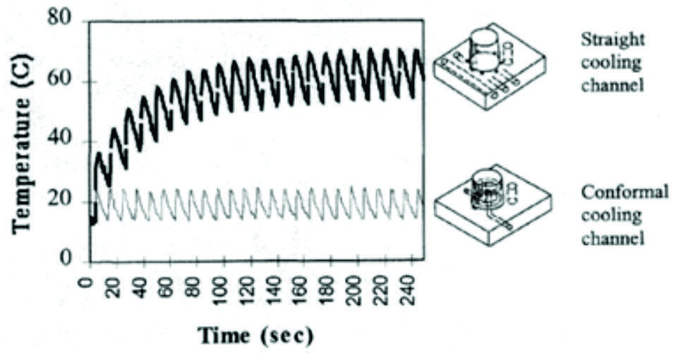
Conformal cooling moulds have curved cooling channels that conform closely to part geometry or contours and their use for an injection mould can reduce cycle time by anywhere from 10% to 40%. The low range gains are possible with little to no engineering analysis; the higher estimates reflect the use of flow analysis, Computational Fluid Dynamics (CFD) and Finite Element Analysis (FEA).

Whilst conformal cooling solutions can significantly reduce the total cost of production by lowering mould cycle times, they also require sophisticated mould designs. A well-designed conformal cooling mould typically has a wide variety of unconventional curves, twists and shapes that must be precisely placed. Once designed, these complicated moulds must be manufactured to the same standards as any other mould.
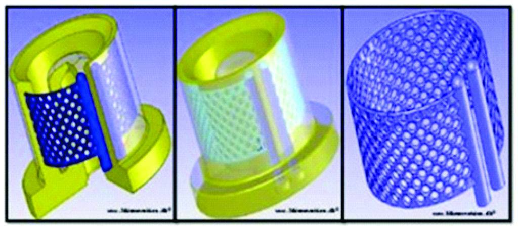
By using non-traditional manufacturing method such as laser sintering, cooling channel can be made in arbitrary geometry to fit the complex product contour. This brings a better cooling efficiency and shorter cycle time.
Direct Metal Laser Sintering (DMLS) is a very popular way these days. EOS and Matsuura are two famous manufacturers of laser sintering machines. Another method is Vacuum Brazing which can also be use for manufacturing of conformal cooling inserts.
Injection Moulding problem solution using Conformal Cooling
Traditional Injection Moulding process faces a lot of issues such as: Sink Marks, Warpage, and Cycle Time. Both Sink Marks and Warpage can reduce product quality which may even cause part rejection from customer side.
Reasons for Sink Marks:
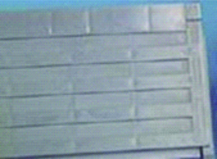
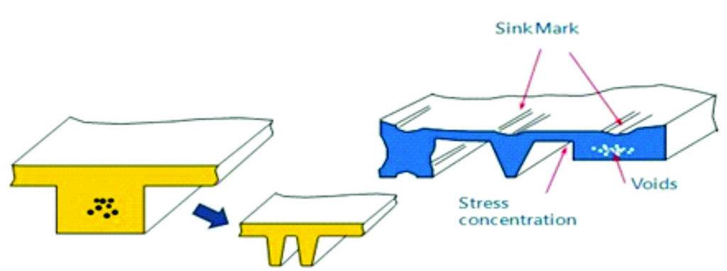
Non-uniform volume shrinkage due to thickness variation such as ribs and boss are commonly seen on products for either functionality or strength reinforcement purposes. These designs can lead problems such as sink mark, void, and stress concentration.
Possible Solution for Sink Marks:
Conformal cooling is one of the solutions for sink mark. Part re-designing is suggested for minimization of sink marks which can be better comprehend from the following figure:
Reasons for Warpage:
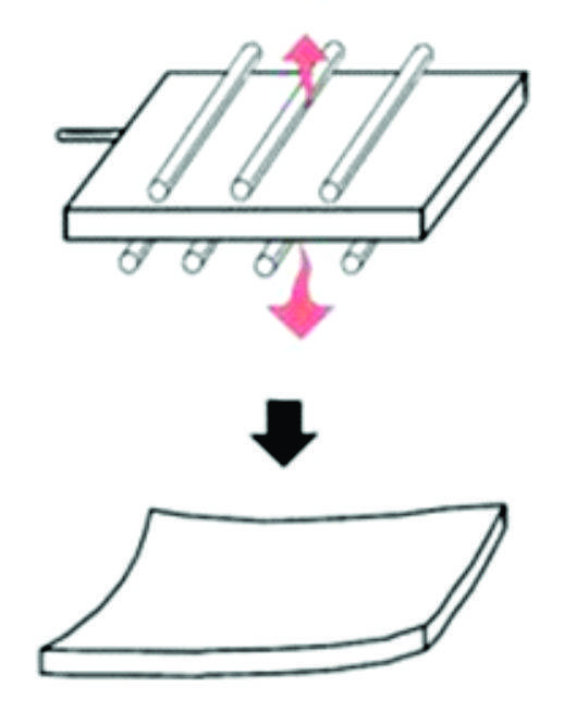
There are three major reasons for warpage i.e. Packing Pressure, Temperature Distribution, Fiber Orientation. One of them is temperature difference as shown in the picture.
Possible Solution for Sink Marks:
So, if the temperatures at core and cavity side and be more even, warpage can be reduced. Conformal cooling can help in maintaining even temperature differences along the component domain.
Reasons for Cycle Time:
Cycle time plays a vital role in Injection Moulding process because it is one of the factors which will govern overall profit. Let us take an example of a component which takes around 15 seconds for completion of process cycle including Clamping, Injection, etc. We can say that time for one component to get completed is 15 seconds i.e. Cycle Time is 15 seconds. Total around 5760 parts can be fabricated per day which leads to 2,102,400 parts in a year.
Now if by any means, let us suppose by incorporating conformal cooling in our existed design, we are able to drop down the cycle time to 12 seconds (i.e. by 20%). Then our production values will change from 5760 parts to 7200 parts in a day and 2,102,400 parts to 2,628,000 parts in a year. A difference of ~520,000 parts makes a lot of sense. So, by employing conformal cooling we can achieve mould cooling at a faster rate which can increase overall yearly profit.
Table 1. Evaluation of Net Profit a customer can earn by adoption of Conformal Cooling
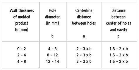
Design Parameters for Conformal Cooling
Basically there are three important parameters for conformal cooling design which are as follows:
- Distance between pipes: a
- Pipe diameter: b
- Distance between pipe and cavity: c
Theoretically, c should be as smaller as possible. And the values of a and b are dependent. However, mould strength and life cycle is a great concern. So, there is an experimental design guideline for the three parameters as shown in the figure below.
Fig. 9. Design guidelines for conformal cooling channel design.
With DMLS, the cross section shape of the pipes can be changed, not necessary to be circular. The feasibility criterion supposes a cross section, which is self supporting. This means the angle of overhanging areas should be above 40° to horizontal.
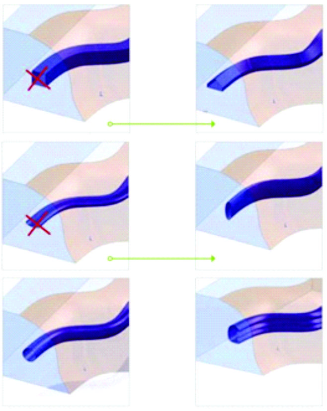
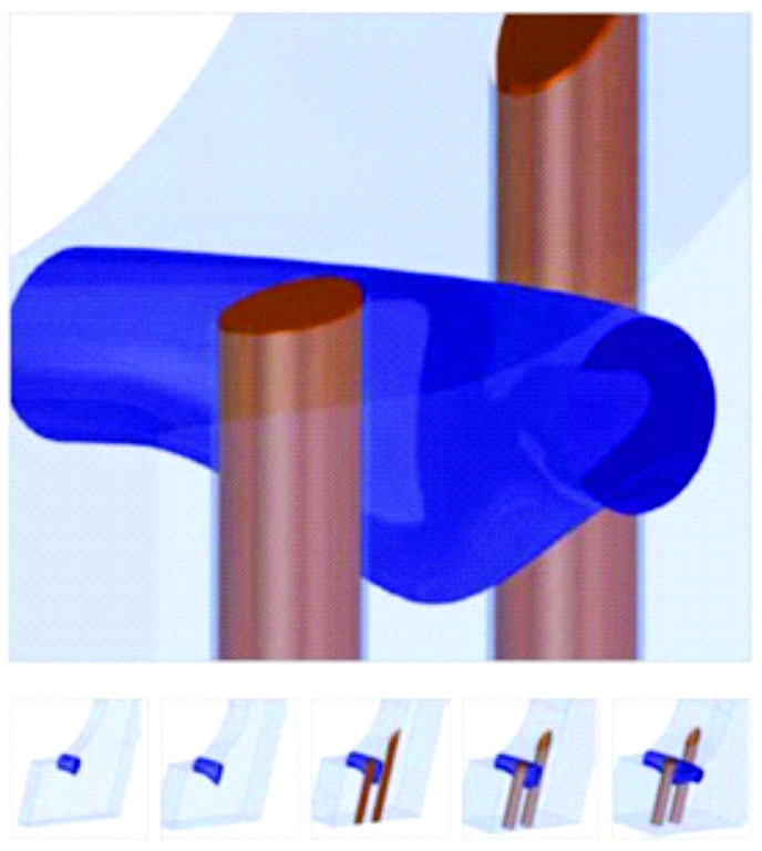
The cooling performance can be increased due to the ribbed shape and the higher expected turbulence in the channel (higher Reynolds number). Two ejectors are bypassed in the space between without pushing the remaining wall thickness to a critical limit.
“Education is the key. You need to educate your customers on what they can gain through AM – and also help them realize that if you want major improvements things just have to change.”
Shubham Saxena is a Process Expert for Additive Manufacturing/3D-Printing at PROTIQ India. PROTIQ is A Phoenix Contact spin-off company which majorly focuses upon Additive Manufacturing and allied Technologies. He has a diverse background in Aerospace, Automotive and Metal Additive Manufacturing.

