[ihc-hide-content ihc_mb_type=”show” ihc_mb_who=”reg” ihc_mb_template=”3″ ]
[vc_row][vc_column][vc_column_text]Credits – www.3ders.org
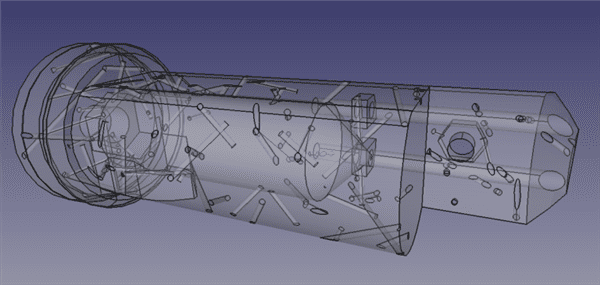
The organization that’s arguably most responsible for that sense of community in the 3D printing space is the RepRap project, and they’ve just given us another nugget of wisdom. Dr. Adrian Bowyer at RepRap Ltd wrote a FreeCAD Python macro that randomly inserts angled, hollow cylinders through a digital model to increase the part’s strength for 3D printing.
Generally, the more solid a part, the stronger it is. So adding hollow tubes throughout a part seems like a counterintuitive way to strengthen it. The theory behind this rests on the way infill is generated by slicing programs; infill is the inside of a 3D print that can’t be seen, and it’s a measure of spatial density/solidity. 3D prints on FDM (fused deposition modeling) are usually not printed solid because it’s inefficient to do so, costing more in time and material.
Therefore, slicing programs fill the inside of 3D prints with mostly air by generating patterns of square grids, triangles, or honeycomb, the most popular. Users set the density of infill as a percentage, with 0% creating a part that’s a completely hollow shell and 100% creating a totally solid part. The great majority of 3D prints are set to have an infill of between 15% and 30% as it’s a nice combination of light and strong. One of the weaknesses of most slicers is that only one infill density can be applied to a part; the density is always uniformly dispersed throughout the 3D print.
Unfortunately, mechanical stress is very rarely uniformly dispersed across that 3D print. Stress is generally greater in specific areas where weight or pressure is applied. Boosting the strength of those stressed spots by cranking up the infill would increase the density of the entire part and use more material than is technically required. Dr. Bowyer wanted to add density in select areas, and the hollow cylinders achieve this because of the plastic used to create the walls of the tubes. While the tubes are themselves hollow, their walls are solid. Angling the tubes spreads the solidity across multiple axis while also offering some protection against delamination (the separation of layers).[/vc_column_text][vc_single_image image=”4506″ img_size=”full” alignment=”center”][vc_single_image image=”4507″ img_size=”full” alignment=”center”][vc_column_text]To test whether the tubes actually increase strength, Dr. Bowyer 3D printed two versions of the same part: one with hollow tubes added at the stress point (as determined by FreeCAD’s finite element analysis (FEA) tool) and one without. The same weight was applied to both and, sure enough, the one with the tubes was 54% more resistant to bending. By printing both parts with 20% infill, the comparison is illuminating yet incomplete. The addition of the tubes does increase the plastic usage of that part, so a more fair comparison would be to increase the infill of the part without the tubes to match the plastic usage of the one with the tubes. It’s likely the results will still strongly favor the tubes, but it’d be nice to know for science.[/vc_column_text][vc_single_image image=”4508″ img_size=”full” alignment=”center”][vc_single_image image=”4509″ img_size=”full” alignment=”center”][vc_column_text]Dr. Bowyer plans to write a script that will automatically insert the tubes where the FEA tool indicates stress points. Some slicers such as Simplify3D have already implemented ways of increasing the infill of different areas of a part, but only vertically, which is only so useful. Seeing Dr. Bowyer’s script applied directly to a slicer would be a major upgrade.[/vc_column_text][/vc_column][/vc_row]
[/ihc-hide-content]


