


Developments of designing tools have created a paradigm shift, both in the architectural and automotive industry. Traditional stone/brick-based architectures are being replaced by modern skyscrapers and bulky automotive parts by light-weight composite structures. In addition, rapid industrialization across the world has increased the demand of time, energy and cost efficient manufacturing methods. The conventional design approaches are no longer suitable for modern intricate designs and high-end technological applications, while the state-of-the-art additive manufacturing or 3D printing technology are opening new windows of ideas and pulling off the design constraints.
Any component of an assembly starting from a basic screw to an aerodynamically-efficient airplane wing weighs in surplus, unless it has been topologically optimized. Any extra weight means excess material, production and transportation costs, which hampers the energy efficiency and the environment. Topology optimization avails the designing tools for durable and light-weight components for a wide range of applications. One can define the objectives and set the constraints such as material thickness and exclusion area. Based on the applied controls like loads and supports at various locations of the material volume, the software then finds the optimized shape. This helps the users to easily perform light-weighting of structures and design complex shapes. By incorporating this optimized material distribution tool in the field of additive manufacturing, the range of manufactured parts can be widened from aesthetically pleasing building blocks to intricate bones and tissues for biomedical applications.
Available software for topology optimization
Although topology optimization is still under development phase, currently every major design software developer has included topology optimization in their main package for additive manufacturing. Some well-known softwares are: 3-matic from Materialise, Netfabb and fusin360 from Autodesk, Abaqus and Solidworks from Dassault Systems and Ansys Mechanical [1, 2, 3]. There are some new names in the market as well like Sciart and Paretowork, developed at the University of Wisconsin–Madison, USA, for topology optimization.
Some enthusiastic researchers and developers are also making their own codes for topology optimization such as K. Suresh from University of Wisconsin–Madison, N. Strömberg from Obero–Sweden and Z. H. Zuo, from RMIT.
Where Topology Optimization fits in the design cycle of DFAM?
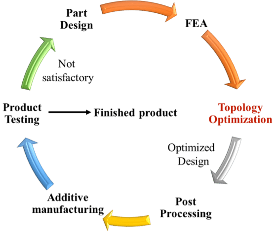
Design for Additive Manufacturing (DFAM) is a quite challenging task for the designers. The entire process works in a cycle (shown in Figure 1) starting with 3-dimensional (3D) modeling of component in a design software i.e. part designing, followed by finite element analysis (FEA), topology optimization, post processing and finally additive manufacturing of the designed parts and product testing. Topology optimization itself is a long iterative process for finding the best optimum design. Mostly, topology optimized designs have some imperfections due to which anticipated purpose of parts cannot be fulfilled, e.g. island areas (which are not connected with the part) in the optimized design. Hence, for removing this kind of imperfections, post-processing of the optimized design is required before 3D printing.
How it works? Need of FEA before Topology Optimization
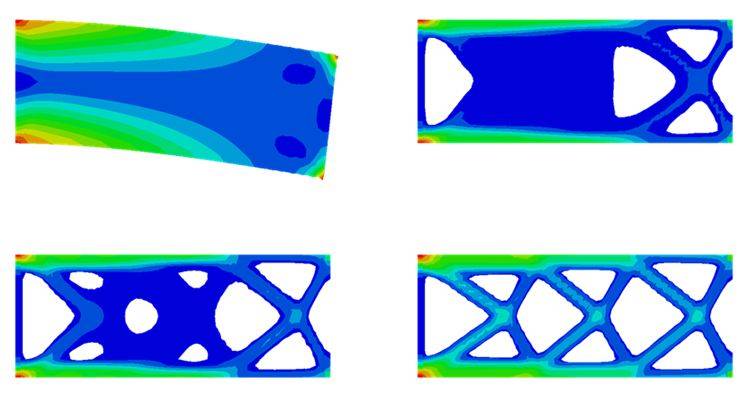
As mentioned before, the first step of the whole cycle of DFAM is the part design, which is also a major step. The required design is first drawn in any CAD modeling software and the original design is then imported in the FEA software with the help of a neutral file format like IGES and STEP. In the second step, FEA is executed for structural analysis with the given loading conditions to analyze the stress and displacement distribution. This is followed by the topology optimization where the algorithm eliminates material from spaces that does not considerably contribute to carry the applied loads, based on the stress and displacement distribution.
Based on topology optimization result, the part is then remodelled in CAD software if required. The new CAD model is again tested with FEA to carry the loads and to fulfill the design requirements. Once the model passes the verification step, physical modelling is carried out using any of physical prototyping methods. The physically modelled parts also need to be verified before arranging the optimized design parts for the final additive manufacturing step.
In this long iterative process, FEA plays a key role without which topology optimization can’t be performed. In fact, the algorithms for topology optimization are written considering FEM at center. By taking inputs from FEA results and verifying them with material properties, algorithm starts remodelling the design by deleting elements. It takes quite a long time to complete the topology optimization problems.
Topology optimization is the best example of Artificial Intelligence in the field of design process. It has the potential to eliminate the requirement of a great human mind for designing best suitable optimal part in the near future.
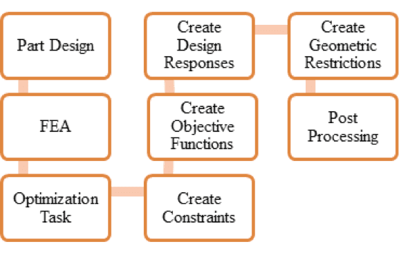
After part designing and FEA, optimization is performed using the following optimization module (shown in Figure 2).
Optimization Task
Three types of optimization task are generally available in the optimization modules: (1) Topology Optimization, (2) Shape Optimization and (3) Size Optimization. User can specify the design parameters at this step.
The inputs to the optimization are called design responses. Some common design responses are stiffness, stresses, eigen frequencies and displacements [4]. The design response is always associated with a region of the model. It is a single scalar value that is extracted from an optimization. The optimization module can extract data from output database and calculate the design response. For example, the total strain energy of the model is a design response which is the measure of its flexibility.
An objective function defines the objective of the optimization. For example, for maximizing the stiffness, the objective function of the optimization can be set as the total strain energy of the model. The objective function is extracted from a design response, such as the lowest eigen frequencies or the minimum stress.
Constraints define the changes that optimization module can apply to the topology or the shape of the model during the optimization. Constraint restricts the value of a design response. For example, if the user wants to constraint the volume of the optimized model to be 40% of the original volume or to set the maximum absolute displacement in a region to not exceed 0.5 mm, it can be done at this stage. Satisfying the constraints has priority over the minimization or maximization of the objective function.
A geometric restriction places restriction on the changes that the optimization module can make to the topology of the model. It includes the frozen regions from which material cannot be removed and manufacturing constraints like restrictions on cavities and undercuts.
Algorithms for Topology Optimization
Topology optimization is a very time-consuming process. It takes numerous iterations to achieve optimized design. For real life solutions, the computational time might take a couple of weeks. Many algorithms have been used for topology optimization such as SIMP (Solid Isotropic Material/Microstructure with Penalization), BESO (Bi-directional Evolutionary Structural Optimization), Level- Set Method, Pareto optimization, Genetic Algorithm etc. SIMP and BESO are the most popular approach in topology optimization, while Pareto optimization algorithm takes the least time required for the same optimization results.
Next Generation Topology Optimization
Whereas topology optimization has been successfully applied in structural mechanics for more than two decades, its application to systems with fluid flow has not been investigated until last decade. More recently, topology optimization has also demonstrated its merit for optimizing the lay-out of systems with steady and unsteady (laminar) incompressible flow. On the other hand, topology optimization for the combination of flow and heat transfer is a new research domain.
Developing compact heat sinks for electronics cooling is another new area of research. Topology optimization of heat sinks allows designing novel and more efficient cooling configurations that can be fitted to many specific applications. Researchers are working towards topology optimization methods based on two-dimensional physical models for compact electronics cooling and 3d designing of heat sinks with extended surfaces.
Multi-material topology optimization is an emerging area, in which advantage of 3d printing techniques can be fully utilized. In this different materials can be topologically placed at the finest suitable place. Multi-material additive manufacturing is quite popular now days, by using multi-material topology optimization it can achieve new heights. Metal AM techniques like LENS can utilize its full capability by multi-material topology optimization. In this area significant work had been done by Prof. K. Suresh of University of Wisconsin [5].
Topology Optimization is a mathematical approach for getting the optimized design. It started as a mathematical investigation using the principle of maxima and minima. In the last two decades, it has found its application in structural optimization. With the advancement of computational tools and additive manufacturing technologies, it has become an emerging area of research with the involvement of research-giants worldwide. Structural topology optimization module is now well adapted by major design software developers, but still there are many areas need to be investigated like multi-material topology optimization, fluid-structure topology optimization and fluid-thermal topology optimization. With the incorporation of these areas in the topology optimization module coupled by additive manufacturing, the next generation of designing and manufacturing by artificial intelligence is not so far.
References
- Autodesk Netfabb, https://www.autodesk.com/products/netfabb/overview
- Dassault Tosca, https://www.3ds.com/products-services/simulia/products/tosca/
- Materialise 3matic, https://www.materialise.com/en/software/3-matic
- Abaqus topology optimization module, https://www.3ds.com/fileadmin/PRODUCTS-SERVICES/SIMULIA/RESOURCES/SIMULIA-Abaqus-Topology-Optimization-Module.pdf
- Taheri, A. H., Suresh, K., “An isogeometric approach to topology optimization of multi-material and functionally graded structures,” International Journal of Numerical Methods in Engineering, Volume 109, Issue 5, pp:668–696, 2017.


