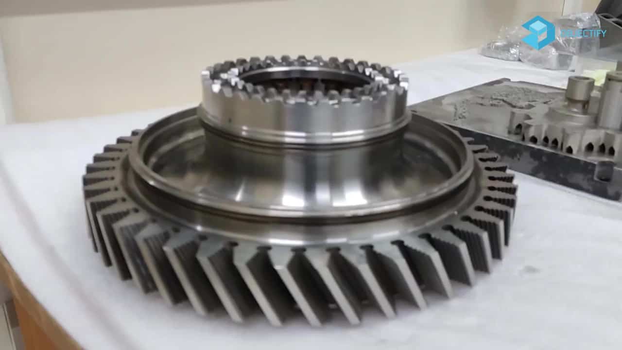
Additive manufacturing (AM) is highly suited for the design and manufacture of manifolds due to its ability to build internal features and passageways.
Objectify Technologies has collaborated with a customer to redesign their current hydraulic block manifold with Additive manufacturing in mind.
The main goal of the 3D Printing project was to reduce the mass of the component whilst retaining its robustness. Due to the increased design freedom associated with AM, an opportunity to increase the efficiency of the flow paths was also identified.
We’re going to share with you how Objectify Technologies optimize the given design by the company to reduce the weight while considering the loading constraints.
The Aerospace Industry is the research, development, and manufacture of flight vehicles and space crafts. It produces Airplanes, spaceships, uncrewed aerial vehicles (UAVs), etc. Technical innovation is the trademark of this industry.
In the aerospace industry, efficiency is a major concern; one way to increase efficiency is by reducing weight of the part.
What is a hydraulic block manifold?
Hydraulic Manifold is used in the aerospace industry to regulate the flow of fluid in a Hydraulic system which helps us control the transfer of power between actuators, pumps and other components in the system.
Traditional manufacture of hydraulic block manifolds
Traditionally, hydraulic block manifolds are manufactured from an aluminium alloy or stainless steel billet which has been cut and machined to size, followed by drilling to create the flow pathways. Specialised tooling is often needed due to the complex drilling that is required. Passages require blanking plugs to properly direct flow through the system.
The nature of the manufacturing process results in abrupt angled junctions between flow paths which can cause flow separation and/or stagnation – a major contributor to efficiency loss.
What material is used to print the hydraulic block manifold?
The material used to build is an age-hardening cast aluminum alloy that provides good hardness, strength and dynamic toughness.
Aluminium alloy manifolds are generally less costly due to lower material costs and ease of machining, however they can be less abrasion resistant, and so any loose particles in the flow will abrade the surface and increase wear. For this reason, stainless steel manifolds are sometimes more desirable, however due to the higher density and hardness of stainless steel compared to aluminium alloy these come with a significant weight increase and added cost of machining.
Benefits of AM for the design and manufacture of Hydraulic manifolds:
- Optimised flow paths for a more efficient component functionality
- Reduction in the requirement for fixturing
- Minimal requirement for removable support structures
- Significant weight reduction is achievable
- No requirement for block extraction passages
- With full design freedom a manifold can be designed to pack into a significantly smaller volume
Direct benefits to customer:
- Mass reduction of up to 30%
- Single piece construction, fewer opportunities for defects
- Rapid design and development iterations
- Compatibility with existing design
- Improved flow efficiency of up to 60%
First design iteration
The previously provided part design is modified into a new one by design optimization by using simulation software –
Rhinoceros 3D >> Design Modification
MSC Apex >> Design Optimization
Materialize Magics >> Data Preparation
Simu fact Additive>> Build Simulation
by elimination of all the unnecessary drill channels and substituting it with more simpler designs, by modification of critical areas and redesign of internal channels for manufacturability by Additive Manufacturing in the considered orientation.
Results summary
| Design stage | Material | Mass (kg) |
| Original hydraulic manifold | Aluminum alloy | 21 |
| Design for AM | Aluminum alloy | 14.9 |
The modified design is then put through simulation. After final iteration Maximum Stress on Component was observed to be “267 Mega Pascal”.
The original weight of the manifold was 21 Kilograms. We were able to reduce its weight by “6.1 Kilograms” which is about “30%” of the initial weight.
The final weight after optimization was “14.9 Kilograms”.
Final changes are made to the design and are made ready to print by adding appropriate stocks and supports to the design. And is fed to the 3D printing machine for printing.
After the printing is completed and the cooldown time, the part is taken out; post processing activities begin. Build Plate removal and then manual powder removal is completed.
Then the part is inspected for any defects in the print. The dimensions and quality of the print is checked for any errors.
Thus, we were successfully able to create the hydraulic manifold which is more efficient, simpler structure and lighter in weight using Additive Manufacturing technology.
Subscribe to AM Chronicle Newsletter to stay connected: https://bit.ly/3fBZ1mP
Follow us on LinkedIn: https://bit.ly/3IjhrFq
Visit for more interesting content on additive manufacturing: https://amchronicle.com/
For more information and similar case studies on metal additive manufacturing register for metal additive manufacturing symposium : https://amchronicle.com/metal-additive-manufacturing/


