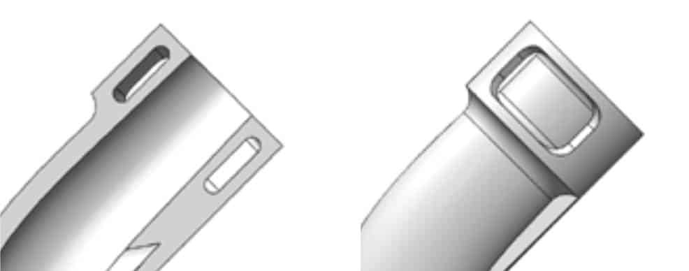
Channels incorporated for zip-ties in order to ensure performance and guide assembly
For decades, photopolymer additive manufacturing (AM) has been leveraged to accelerate the development of innovative automotive components and systems. However, these parts were largely used for non-functional form and fit evaluations, or as patterns to create parts using a traditional molding or casting approach. This narrow use of the technology was primarily due to former limitations in productivity, material properties over time, or both. Now, 3D Systems is significantly expanding the value proposition of AM through new material development, transforming the technology into an innovative manufacturing method for parts that not only meet performance requirements for automotive conditions, but do so over significantly longer duty cycles. In this application brief you will learn how these materials and technologies can be used in developing and producing complex flexible retention systems in vehicles.
The modern vehicle offers many different propulsion systems working in concert with cooling, climate, infotainment, driver information, security systems, and more. All of these require various electrical, energy, and fluid transfers throughout the chassis, body, and interior. These transfers involve routing through limited packaging spaces and challenging operational environments. In many cases the design of these retention or routing components is dependent on features that are produced in smaller volumes due to vehicle customization. Small lot sizes make traditional tooling costs prohibitive. These constraints have posed a seemingly impossible challenge for engineers trying to deliver robust design solutions in time for product launch — until now.
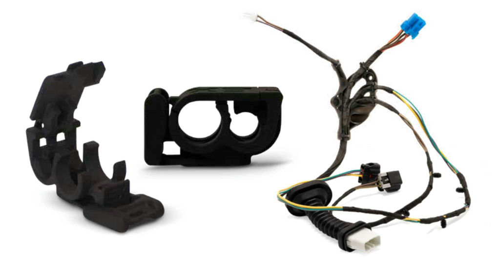
Examples of AM Retention Solutions
Retention devices are found throughout a vehicle, and service the movement of electrical/EDS energy, coolant fluids, washer fluids, pneumatic and vacuum energy, etc. In addition to routing energy and fluids through the system, they often also integrate components like power distribution elements (i.e. relays, fuses, solid state devices, etc.). You will find examples of these types of components throughout this brief.
Key Drivers of AM for Flexible and Fluid Retention Systems
Additive manufacturing allows for greater design freedom to incorporate multiple components and features into a single part. Packaging space is often a premium for these types of components, so utilizing and conforming to complex environments is critical. This application not only improves assembly efficiency and part quality, but also increases packaging efficiency.
MATERIALS SUITABLE FOR FUNCTIONAL LIFECYCLE
Photopolymer materials that are suitable for functional applications over many years of automotive duty cycles are required. 3D Systems offers a range of materials tailored to specific applications with respect to mechanical properties, surface quality, and environmental robustness.
FLEXIBLE PRODUCTION FOR RAPID ITERATION
Photopolymer additive manufacturing solutions provide the productivity, quality, and fidelity to meet automotive needs. This includes both functional performance as well as aesthetic quality to meet design intent.
LOW VOLUME – HIGH VALUE PART ECONOMICS
Additive manufacturing allows for production of tailored designs to meet complex packaging and functional challenges. Elimination of traditional tooling costs and lead time means more iteration, faster time-to-market, and optimized design cost for lower volumes.
Advantages of Using AM
Workflow Solution & Best Practices
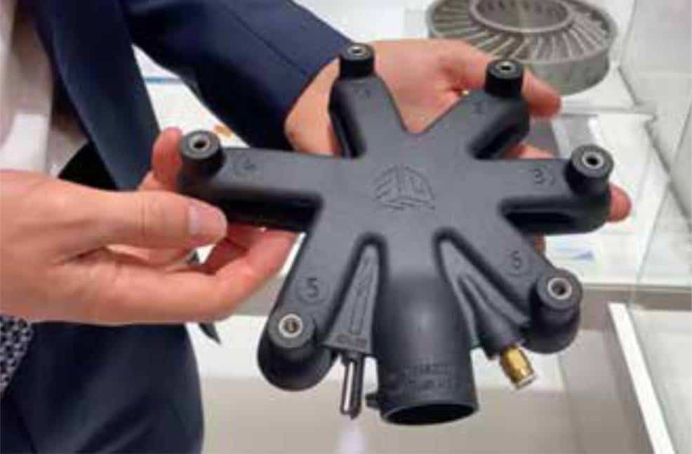
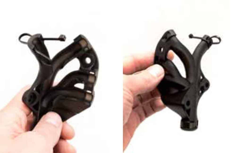
Example Part: Harness Retention Component
Technology: Figure 4
Printer: Figure 4® Modular
Material: Figure 4® Rigid 140C Black
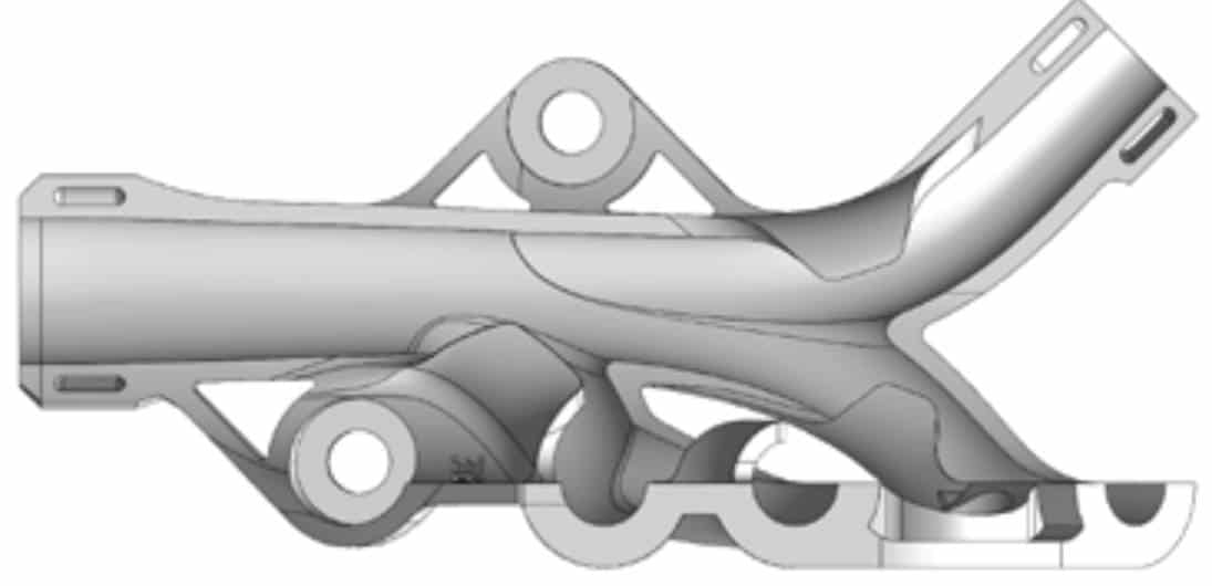
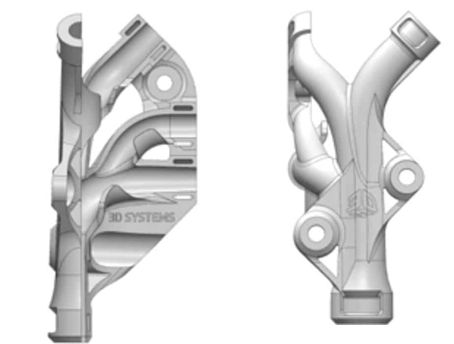
Functionality: The harness retention component is responsible for directing and holding harness bundles through a complex route or path in the vehicle. This is often due to very limited packaging space, a challenging environment, complexity of multiple take-outs, etc. The retention device includes complex design features such as push pins, zip ties, tape channels, and the like. In some components, closes, caps, or covers are incorporated to fully cover the routed harness.
Post-Processing: ProCure 750 UV Finisher, part washing equipment, part finishing equipment and tools (i.e. for support removal)
1. Design for Additive Tips
Considerations when designing for additive manufacturing (DfAM) are sometimes dependent on your specific application and the features that you want to incorporate. However, many guidelines are broadly applicable, regardless of how your retention system will specifically be used. As indicated, the process can be improved considerably with regards to efficiency and quality if DfAM principles are guiding your decisions from the start.
CONSOLIDATING PARTS AND FEATURES
Fluid Junctions: Fluid channels and retention can be incorporated directly into retention systems using AM to eliminate separate T components and additional retention. This means that take-outs for these can be optimized beyond traditional 90-/30-/45-/60-degree angles.
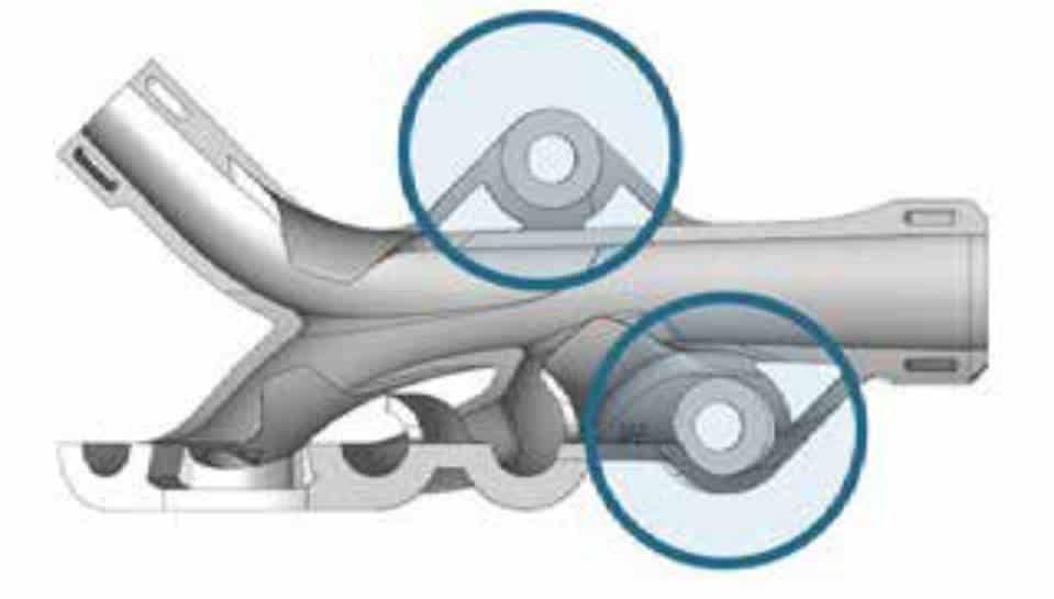
Integrated Stand-Offs: Some components require stand-offs or legs to effectively position and assemble the system in place. With additive manufacturing, these stand-offs can be optimized for the package by eliminating the restrictions on draw direction and draft angles that are typically found in molded designs and leveraging optimal wall thickness for structural performance.
Incorporated EDS Components: Solid-state or traditional EDS components can be designed into the component with optimized package and orientation, unconstrained by traditional molding restrictions of draw direction and draft angles.
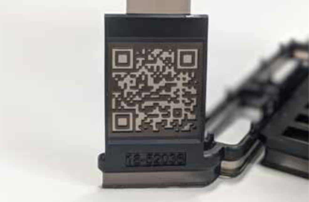
QR Codes: Incorporate custom QR codes into the part design to track part and/or production lot information.
INCORPORATING ADDITIONAL RETENTION FEATURES
Standard Push Pin/J-Clip Features: Using standard retention components often allows for improved in-field serviceability. Designs for additive manufacturing can easily incorporate standard holes and features for securing these components in place upon assembly and service. The initial assembly can incorporate some of these features to consolidate components for release and assembly while allowing service to remove and replace them with off-the-shelf components as needed. For instance, printing the push pins in position in design while allowing them to be easily removed and replaced in the field through sacrificial features.
Zip-Tie Channels: Sometimes zip-ties may be incorporated as a secondary or service-oriented feature to secure components together. Specific channels can easily be incorporated to ensure performance and guide assembly or service in placing these, especially if retained components have sensitive features to protect.
Tape Channels: Tape is sometimes used as a secondary or service-oriented feature to secure components together. Specific channels can easily be incorporated to ensure performance and guide placement in assembly and service.
Trough Design: Leverage additive manufacturing and design freedom to more efficiently conform to and leverage available space in sheet metal troughs. Because the cross-section of these is often limited, space utilization is critical.
Assembly Aids: With the design freedom of additive manufacturing, engineers can incorporate assembly features and poke-yokes without the constraints of traditional manufacturing methods. This makes routing, assembly, and service more reliable and of higher quality.
INTEGRATED COVERS
Frequently, the system holding the harness or flexible components will need to incorporate a cover in order to fully secure the harness, tube, or cable in place. In these cases, integrated covers can be leveraged that include both “living hinges” and more traditional hinge-pin designs. Even in the case of traditional hinge-pin designs, AM production approaches can reduce or eliminate assembly operations. “Living hinges” are likely to be designed to be flexible enough to easily close and secure through snap fits. Once assembled, the snap fits will be the primary mechanism to hold the cover securely in place.
2. File Preparation
*.stl File Resolution: When exporting the *.stl file from the CAD package, consider the balance between resolution and file size. Fine features should be of high enough resolution to guarantee functional requirements, and low enough to ensure an efficient data workflow and file preparation. As a general guideline, we suggest 0.01 mm chord height.
Part Orientation and Design for AM: To ensure optimal surface quality, part orientation must be taken into account. Whenever possible, engineering and design should consider and include build/support features and orientation in the native design process. This will significantly speed up the process for build preparation from the start. For example: point major features in
the same direction where possible so they can be self-supporting, which eliminates the need for additional support features. Stacking and integrating support pads into the design from the start will also significantly reduce build preparation and post-processing time, thus increasing the efficiency and quality of the produced part. In addition, adding fillets in certain areas may eliminate or reduce the need for support structures while also reducing stress concentrations.
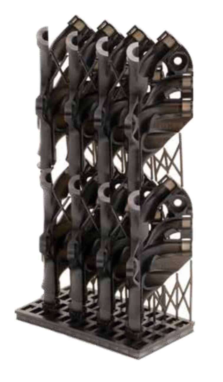
Software Features to Optimize Designs: Leverage the advanced part stacking features of 3D Sprint for more productive manufacturing. These solutions can also provide texturing for production-level surfaces.
Generate and Add QR Codes: Design teams can leverage their QR-code management solutions or generate QR codes using a free app to create the desired *.jpeg. This can be positioned and wrapped on the part surface to incorporate the QR features in 3D on the surface. A QR code can also be integrated as part of the assembly stack to identify the lot and even scan the code from outside the equipment during the build.
3. Printing Set Up & Parameters
3D Sprint® software is an advanced, single-interface software for intuitive file preparation, editing, printing, and management, and contains fully developed and validated print parameters for all 3D Systems materials. While all parameters are customizable, we recommend our default parameters. For advice on customized parameters, contact the experts in our Application Innovation Group.
FEATURE SPECIFICATIONS
Achievable minimum feature sizes are highly dependent on the combination of additive manufacturing technology, specific material, design, and print orientation. For a clear assessment of the feasibility of a specific component, please reach out to the 3D Systems’ Application Innovation Group.
This harness retention component was produced with Figure 4® printing technology and Figure 4® Rigid 140C Black material. Wall thickness was designed with 2 mm, going down to 0.8 mm at the thinnest sections.
Holes and channels: Achievable minimum hole diameters are dependent on the aspect ratio of diameter and depth/ length. For example, a 0.5 mm diameter hole that is 5 mm long, may be easier to realize than a 0.5 mm hole that is 20 mm long.
When incorporating features such as blind holes and channels, it can be preferable to include a vent to allow for optimal draining and faster, more effective post-processing.
Wall thickness: Wall thickness is a function of the design requirements of the component, but the system can achieve detail down to less than 0.5 mm.
4. Post-Processing
The steps for preparing flexible component retention vary from user to user, but the basic steps include:
Step 1: Washing parts to remove excess material (on the platform, if possible); make sure there are allowances for the stacks to let cleaning solutions flow through effectively
Step 2: UV post-curing (on the platform, if possible)
Step 3: Removing parts from the platform and removing supports
Step 4: Detail cleaning, as required
5. Solution Components
MATERIALS
Accura® AMX™ Rigid Black (SLA): Production-grade stereolithography resin featuring long-term environmental stability for large-scale plastic parts with demanding mechanical performance requirements and exceptional surface finish.
Figure 4® TOUGH-BLK 20 (Figure 4): A strong material with industry-leading environmental stability. Parts feature an exceptional surface finish, high precision, durability, and long-term stability for fast, high-performance prototyping and production.
Figure 4® Rigid 140C Black (Figure 4): A rigid heatresistant material combining high strength and hig
Figure 4® High Temp 150C FR Black (Figure 4): UL94 V0 rated flame-retardant black plastic with >150˚C heat deflection temperature.
Figure 4® FLEX-BLK 10 (Figure 4): A flexible material for the production of exceptionally durable polypropylene-like parts for a wide variety of prototyping, functional testing, and low volume production applications.
Figure 4® Tough 65C Black (Figure 4): Black plastic for long-term use parts with a good combination of impact strength, elongation, and tensile strength.
DuraForm® EX BLK (SLS): Tough, oil- and fatigueresistant nylon 11-based plastic engineered for additive manufacturing to withstand repeated abuse in harsh, frequent-use environments.
PRINTERS
ProX® 800 (SLA) – SLA quality at high throughput to address the broadest range of applications.
Figure 4® Standalone and Figure 4® Modular: Figure 4 Standalone delivers ultra-fast and affordable 3D printing for same day prototyping and low-volume production. Figure 4 Modular is a scalable, semi-automated 3D manufacturing solution designed to scale with growth. It has auto-refill capability and additional Z-axis height for more production stacking.
ProX® SLS 6100 (SLS): Production-grade nylon 3D printer delivering best-in-class part quality, fast build times, and automated production tools.
sPro 140 and sPro 230 (SLS): Medium and large capacity SLS printers for high throughput of tough and durable thermoplastic parts.
SOFTWARE
3D Sprint® Software: Advanced, single-interface software for intuitive file preparation, editing, printing, and management. 3D Sprint is included with 3D Systems’ plastic 3D printers.
Geomagic® Freeform® Software: The industry’s most comprehensive, organic, hybrid design software for complex surfacing and texturing.
POST-PROCESSING
ProCure 750 UV Finisher: Achieves final curing of SLA parts through uniform exposure to UV light during a specific period of time.
LC-3DPrint Box: Post-cures Figure 4 parts to obtain final material properties through quick and uniform exposure to UV light.
6. Critical Success Factors
The right AM solution is only part of the equation for success. How AM is onboarded, integrated, and implemented all contribute to its impact.
ONBOARDING – TRAINING A TECHNOLOGY CHAMPION
Having at least one trained, in-house AM expert goes a long way in a company’s successful adoption of AM. 3D Systems offers a variety of trainings through our Application Innovation Group to bring your technology champion up to speed to help your company get a running start. 3D Systems customizes training content to your specific needs and guides you in how to use AM to maximize the effectiveness of your retention component applications.
INTEGRATION – TRAINING ON END-TO-END PROCESSES FOR OPTIMIZING EFFECTIVENESS OF AM
3D Systems partners with you throughout the entire AM process, from file set-up to finished part. As part of equipment installation, 3D Systems provides essential knowledge on operating the system, as well as tips and tricks to get the most out of your AM applications.
A strong partnership helps deliver a smooth and effective AM experience, both when working with 3D Systems and interdepartmentally. To maximize the productivity and output of your system, regular communication between the designer, AM expert, and post-processing experts is essential.
IMPLEMENTATION – REALIZING THE ADVANTAGES OF AM
AM delivers tangible impacts to your bottom line for flexible component retention devices by delivering quicker design iterations and optimized manufacturing performance and productivity compared to traditional molded components. Advancements in photopolymer materials by 3D Systems have transformed the long-term stability and performance of parts designed for automotive use.
Traditional Manufacturing
3D Systems
Why 3D Systems
When it comes to choosing an additive manufacturing solution for flexible component retention in automotive, you want to ensure that your systems are packaged efficiently, ensure performance, and deliver with quality throughout the duration of the automotive lifecycle. 3D Systems has developed innovative materials that perform over time, along with an equipment and solutions portfolio that is proven in the automotive industry.
Working closely with all the automotive industry leaders has led to 3D Systems’ development of a complete solution package comprised of integrated hardware, software, and materials, as well as expert application knowledge, including onsite field service. Unlike other 3D printer providers, 3D Systems’ complete solution for developing complex automotive components is the result of constant collaboration with the industry across many applications.
Our hardware has been developed to work with the most advanced photopolymer (SLA) and selective laser sintering (SLS) materials, assuring the performance of our printed parts for automotive use. Our software allows you to quickly modify and set up print files for rapid and accurate printing with accelerated post-processing that enables curing and finishing of parts in hours. Our flexible yet rigid materials deliver high performance in complex environments, providing vehicle programs with the confidence to deliver the most advanced vehicles to meet their customers’ needs over the full span of ownership. Our expertise delivers an excellent AM experience by meeting and exceeding the demands of the key applications you are utilizing to drive your brand, with broad field service coverage to support your nonstop innovation.
Subscribe to AM Chronicle Newsletter to stay connected: https://bit.ly/3fBZ1mP
Follow us on LinkedIn: https://bit.ly/3IjhrFq
Visit for more interesting content on additive manufacturing: https://amchronicle.com/
For more information and similar case studies on metal additive manufacturing register for metal additive manufacturing symposium : https://amchronicle.com/metal-additive-manufacturing/
Researchers have developed a way to consistently produce a special type of stainless steel known…
APF designed to enable superalloy development in direct energy deposition. Nikon has announced the release of…
Schoeller-Bleckmann Oilfield Technology GmbH (SBOT), based in Ternitz, Austria, has completed the first expansion stage…
The companies will work together to develop new standards for the energy industry using cold…
Fortius Metals, a company located in Colorado and specializing in supplying metal wires for additive…
ADNOC Gas has developed one of the energy industry’s largest digital libraries of critical components,…
This website uses cookies.